Preparing for the Final Competition
After struggling with Milestone 4, we summarized the tasks we needed to accomplish to complete our robot for the final competition.
- Integrate radio communication with maze navigation
- Add real-time maze mapping with the FPGA by displaying on the VGA monitor
- Integrate treasure detection
- Add start and end signals
Radio
- We first were able to integrate the radio
- Initially, we changed the format of the data being sent. Previously in lab 4, we sent 3 bits for the row, 2 bits for the column, and 2 bits for data. Now, we sent 7 bits for data represented as 2 bits for treasure, 1 bit for done, and 4 bits for wall location.
Before:unsigned int new_data; // pack bits as follows: // x-coor | y-coor | data // 3 bits | 2 bits | 2 bits unsigned char x = 4; unsigned char y = 3; unsigned char d = 3; // shift bits in order to pack bits, then or them together new_data = x << 4 | y << 2 | d;
After:unsigned int new_data; // pack bits as follows: // row | column | data // 3 bits | 2 bits | 7 bits // data example: // done treasure wall // 1 00 1001 unsigned char row = r; unsigned char col = c; unsigned char wall = detected_wall_loc[r][c][NORTH] << 3 | detected_wall_loc[r][c][EAST] << 2 | detected_wall_loc[r][c][SOUTH] << 1 | detected_wall_loc[r][c][WEST]; unsigned char d = !notDone() << 6 | treas << 4 | (wall & 15); new_data = row << 9 | col << 7 | d; - We tested the new format of the data on two Arduinos. After that worked, we proceeded to integrate this with our dfs
- Initially, we had issues adding radio communication within dfs. Our robot no longer navigated the maze or sensed anything correctly because we were “listening” at the incorrect place.
void radioSend() { // // Ping out role. Repeatedly send the current time // Serial.println(F("radio send")); radio.startListening(); // moved from setup if (role == role_ping_out) { // First, stop listening so we can talk. radio.stopListening(); . . . } . . . radio.startListening(); . . . radio.stopListening(); } - Once we fixed that, our radio communication no longer interfered with maze mapping. However, we couldn’t get the receiver Arduino to indicate that it was receiving (print statements in serial monitor). We realized that was a silly mistake due to not including “printf_begin()” in our code.
FPGA and VGA Display
- From lab 4, we had to make some modifications to display the newly formatted data correctly
- We first tested the implementation by hard-coding a maze like a simulation. Once we were comfortable with that, we remodified the code to display the maze as the receiver Arduino listened to the sender Arduino on the robot.
Start/End Signals
Start Signals:Push Button
- We first added a small push button to our circuit on the robot.
- The push button was connected to analog pin 4, power, and a pull-down resistor of 10kOhms to ground
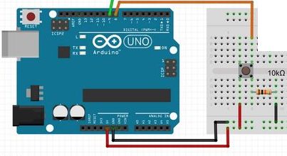
- This was straightforward since the only code that we added was a simple while loop polling analog pin 4 and exiting once the button was pressed
                while(!start) {
                  if (analogRead(4)>500) start = 1;
                }
Microphone (660Hz Detection)
- We connected the microphone to analog pin 5
- For the microphone to detect 660Hz, we created a function micRead() to do the fft frequency detection. We chose to not use free-running mode and to instead simply poll until 660Hz is detected.
- Initially, we still had problem with the fft interfering with our servos. To fix this, we got rid of sei() and cli() from our code, which were likely messing up the clock that also controlled the PWM module on the servo pins.
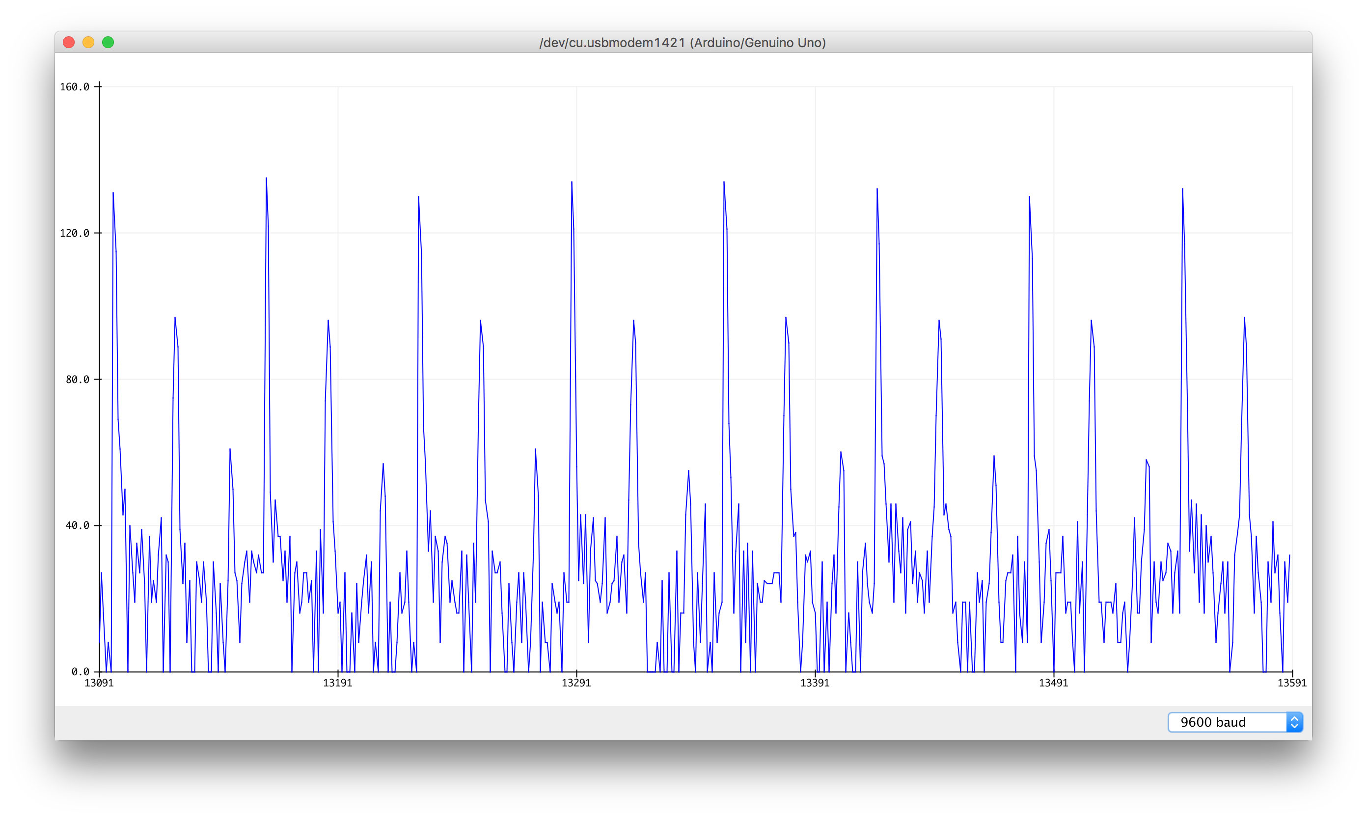
- To get the thresholds, we used the serial plotter first to see if any peaks occurred. We were able to determine that for 660Hz, a consistent peak above occured above 60. Then, we used the serial monitor to print out the values of the fft function and to count which bins the peak occurred in (9 and 10).
boolean micRead() { for (int i = 0 ; i < 256 ; i += 2) { fft_input[i] = analogRead(A5); // <-- NOTE THIS LINE fft_input[i+1] = 0; } fft_window(); // window the data for better frequency response fft_reorder(); // reorder the data before doing the fft fft_run(); // process the data in the fft fft_mag_log(); // take the output of the fft Serial.println("Start"); if(fft_log_out[9] > 70 && fft_log_out[10] > 70){ return true; } else { return false; } } - When micRead() detected 660Hz, it returns true. We added polling analog pin 5 to our while loop from before with the push button.
while(!start) { if (analogRead(4)>500 || micRead()) start = 1; } - Now, if the robot detects the button pushed or 660Hz, it starts
- In order to verify that the robot would not start at other frequencies. We tested varying frequencies within 300Hz above and below 660Hz and did not get any false starts.
Green LED
- We added a green LED to our circuit connected to digital pin 8
void setup() { . . . digitalWrite(8, LOW); } - When the robot is done mapping the maze, we turn digital pin 8 from low to high to signal on the LED
              boolean notDone() {
                  for (int R = 0; R < 5; R++) {
                    for (int C = 0; C < 4; C++) {
                      if (...) {
                        return true;
                      }
                    }
                  }
                  digitalWrite(8, HIGH);
                  return false;
                }
Monitor
- We modified our FPGA code to change the display when the robot is done
wire [7:0] TAN = 8'b111_111_10; // out of bounds not done wire [7:0] BLACK = 8'b000_000_00; // out of bounds done . . . always @ (PIXEL_COORD_X,PIXEL_COORD_Y) begin // Current square color if (!done ...) begin ... PIXEL_COLOR = YELLOW; end else if (done ...) begin PIXEL_COLOR = WHITE; end . . . // Background color else if (...) begin if (done) begin PIXEL_COLOR = BLACK; // out of bounds (background) origin_x = origin_x; origin_y = origin_y; end else begin PIXEL_COLOR = TAN; // out of bounds (background) origin_x = origin_x; origin_y = origin_y; end end end - Here is a demo of our robot wirelessly sending updates to the base station
- When the robot finishes the maze, the monitor changes the background color from white to black
Three-Tone Sound
- We integrated our code from lab 3, which plays 3 different tones
- Now, the speaker plays an arpeggio when the robot is done
              // 3 tones
              localparam CLKDIVIDER_1k = 25000000/622/255;
              localparam CLKDIVIDER_1250 = 25000000/778/255;
              localparam CLKDIVIDER_1500 = 25000000/933/255;
              .
              .
              .
              always @(soundCount) begin
                if (done) begin
                  if (soundCount == 3'b1) out = signal;
                  else if (soundCount == 3'd2) out = signal2;
                  else if (soundCount == 3'd3) out = signal3;
                  else out = 8'b0;
                end
                else out = 8'b0;
              end
              always @(posedge CLK_1k) begin
                ...
              end
              always @(posedge CLK_1250) begin
                ...
              end
              .
              .
              .
              initial begin
                soundCount = 3'b0;
                out = signal;
                counter = 8'd255;
                sin[0]<=8'd128;
                sin[1]<=8'd134;
                sin[2]<=8'd141;
                .
                .
                .
                sin[253]<=8'd115;
                sin[254]<=8'd122;
                sin[255]<=8'd128;
              end
Treasure Detection
- We had trouble with using fft with our treasure detection since it kept interfering with our system.
- We tried to fix this by using interrupts instead. We were able to detect treasures with interrupts. However, we were running low on available pins, and this required digital pins 6 and 7 as comparators, so we decided to scrap the idea.
- After successfully using fft for the microphone 660Hz detection, we wanted to try this method for the treasure detection. However, we were still struggling with the treasure circuitry itself. The amplification circuit wasn’t working very well or consistently despite it working before.
- With little time left to add more to our robot and test it, we weren’t confident in our treasure detection. As a result, our decision to not include treasure detection in our final robot design was our way to prioritize overall accuracy.
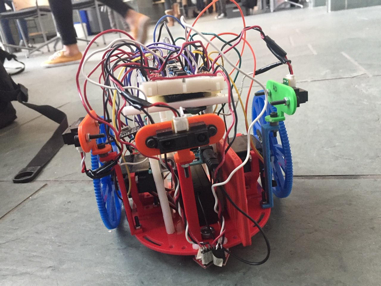
Final Robot Design
Line Sensors
- We have a total of 4 line sensors: 2 for the front, 2 for the side
- The 2 front sensors are close together to detect the line and implement line following.
- The 2 side sensors are our wide sensors for intersection detection.
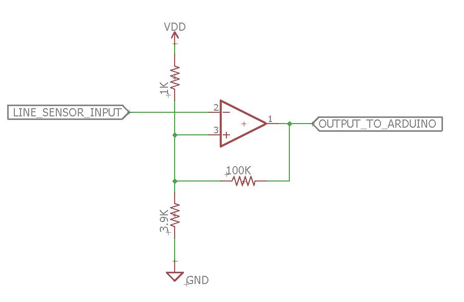
- Initially, we used analog pins for the line sensors. However, we began to run out of available pins. So, we decided to use Schmitt triggers instead.
- The Schmitt triggers we built were inverting Schmitt triggers. We decided to inverting because the non-inverting version required extra circuitry for a reference voltage.
Wall Sensors
- We have a total of 3 wall sensors: 1 mid-range for the front, 2 short-range for the side
- Our decision for which range sensors to use was based on our measurements from milestone 2:
IR Sensor Distance Arduino Reading Long Range 2" 1000+ Long Range 6" 500 - 550 Long Range 12" 370 - 380 Regular 2" 620 - 630 Regular 6" 310 - 330 Regular 12" 170 - 190 Short Range 2" 390 - 405 Short Range 6" 130 - 170 Short Range 12" 60 - 90 - Before, we used Schmitt triggers for the wall sensors. However, our range of detection wasn’t very good. Therefore, we switched the line and wall sensors. Now, the line sensors used Schmitt triggers and the wall sensors used analog pins.
Other
- Our final robot has its chassis base very close to the ground in order to have the center of gravity close to the ground as well. With our large wheels, we believed this to be the best way to structure our robot.
- We chose larger wheels to maximize distance travelled per servo rotation
- Circuitry:
- We designed a PCB for our robot, but we decided against using it because our circuit design changed
- As an alternative, we created a protoboard. However, we realized our treasure detection circuit was incorrect (before we decided to not include treasure detection), so we decided to use our small breadboard until everything was finalized.
- We did create a final protoboard, but we ran out of time to include it on our robot. Since the breadboard worked, we didn’t want to risk messing up connecting the robot too close to the competition.
- We also assembled a base-station for our VGA display. We mounted the FPGA, Arduino, and breadboard on a small piece of wood.
Final System
BB-8

Front:
Side:

Top:

Base Station:
