Objective
The goal of this lab is to figure out the wireless communication between the 2 Arduinos and FPGA.Team Division:
- Radio: Rohit Krishnakumar, Alice Song, Victoria Tu
- FPGA: Meghan Chen, Serena Krech, Michael Yee
Radio Team:
Materials Used:- 2 Nordic nRF24L01+ transceivers
- 2 Arduino Unos (one must be shared with the other sub-team)
- 2 USB A/B cables
- 2 radio breakout boards with headers
Procedure:
- Download the RF24 Arduino library add to Arduino library directory
- Download Getting Started Sketch from the course repository and replaced Getting Started Sketch from RF24 library
- Changed identifier numbers for 2 pipes based on our team (22, 23)
- Programmed both Arduino boards with the Getting Started example
- Modify code to send the maze as a single packet
- Modify code to send new data
1. Download the RF24 Arduino library add to Arduino library directory
2. Download Getting Started Sketch from the course repository and replaced Getting Started Sketch from RF24 library
3. Changed identifier numbers for 2 pipes based on our team (22, 23)
- Used formula from lab4 website page 2(3D+N)+X
- Set the channel numbers for our team by modifying the Arduino code
4. Programmed both Arduino boards with the Getting Started example
- Plug both Arduinos to the laptop
- Select one Arduino to be the transmitter by typing “T” in the serial monitor
- Switched between the serial monitors of each Arduino to see that one was receiving what the other was transmitting
5. Modify code to send the maze as a single packet
- Defined the maze
// Define maze unsigned char maze[4][5] = { 3, 3, 3, 3, 3, 3, 1, 1, 1, 3, 3, 2, 0, 1, 2, 3, 1, 3, 1, 3, //3, 0, 3, 1, 0 }; - Modified sender/transmit side
// Send maze in single payload printf("Now sending the maze!\n"); bool ok = radio.write( maze, sizeof(maze) ); if (ok) printf("ok..."); else printf("failed.\n\r"); - Modified receiver side
// Dump the payloads until we've gotten everything unsigned char got_maze[4][5]; bool done = false; while (!done) { // Fetch the payload, and see if this was the last one. done = radio.read( got_maze, sizeof(got_maze) ); // Print the maze for (int i=0; i < 4; i++) { for (int j=0; j < 5; j++) { printf("%d ", got_maze[i][j]); } printf("\n"); } // Spew it printf("Got payload %lu...",got_time); // Delay just a little bit to let the other unit // make the transition to receiver delay(20); - The serial monitor shows what we expect. The transmitting Arduino sends the payload, and the receiving Arduino gets the maze.
- The RFK library has an Auto-ACK feature
Transmit:
Receive:

6. Modify code to send new data
- Send 3 pieces of information: x-coordinate, y-coordinate, state of current position
- Maze is 4x5, so we define the orientation so that the x-coordinate needs 3 bits, and the y-coordinate needs 2 bits.
- There are 4 different states (unvisited, no wall, wall, treasure), so the data needs 2 bits.
- On the transmitter side, we packed the bits together on using left shift and sent the package as a single payload.
// SENDER SIDE // Define maze unsigned char new_data; // pack bits as follows: // x-coor | y-coor | data // 3 bits | 2 bits | 2 bits // test unsigned char x = 4; unsigned char y = 3; unsigned char d = 3; // shift bits in order to pack bits, then or them together new_data = x << 4 | y << 2 | d; // (4, 3, 3) should give 1001111 or 79 in decimal // Send maze in single payload printf("Now sending new map data!\n"); bool ok = radio.write(&new_data, sizeof(unsigned char) ); if (ok) printf("ok..."); else printf("failed.\n\r"); // Now, continue listening radio.startListening(); - The receiver side can then unpack the bits.
// RECEIVER SIDE unsigned char got_data; bool done = false; while (!done) { // Fetch the payload, and see if this was the last one. done = radio.read(&got_data, sizeof(unsigned char) ); // Spew it printf("Got payload %d...",got_data); // display decimal // Delay just a little bit to let the other unit // make the transition to receiver delay(20); } - The serial monitor verified what we expected, which was to send/receive payload 79 (1001111).
Graphics Team:
Materials Used:- FPGA
- 1 Arduino Uno
- 1 VGA Cable
- 1 VGA Connector
- 1 VGA Switch
- Resistors
- Make grid from lab 3 bigger
- Receive packets from the Arduino
- Highlight the robots current location based on packet information
- Mark explored territory
1. Make grid from lab 3 bigger
- For this step we needed to scale up what was previously written in Lab 3.
- To do so, we extended the size of our color-storing grid_array to be 4 by 5 bits.
- We also used for loops to assign data to each of the squares in the grid, since the previous lab’s implementation individually assigned data to grid squares and was non-scalable.
2. Receive packets from the Arduino
- The Radio team received packets in 7 bits. We chose to use parallel communication for this lab for simplicity.
- In the future, we hope to switch to SPI. This option will reduce the number of connections needed between the arduino and the FPGA.
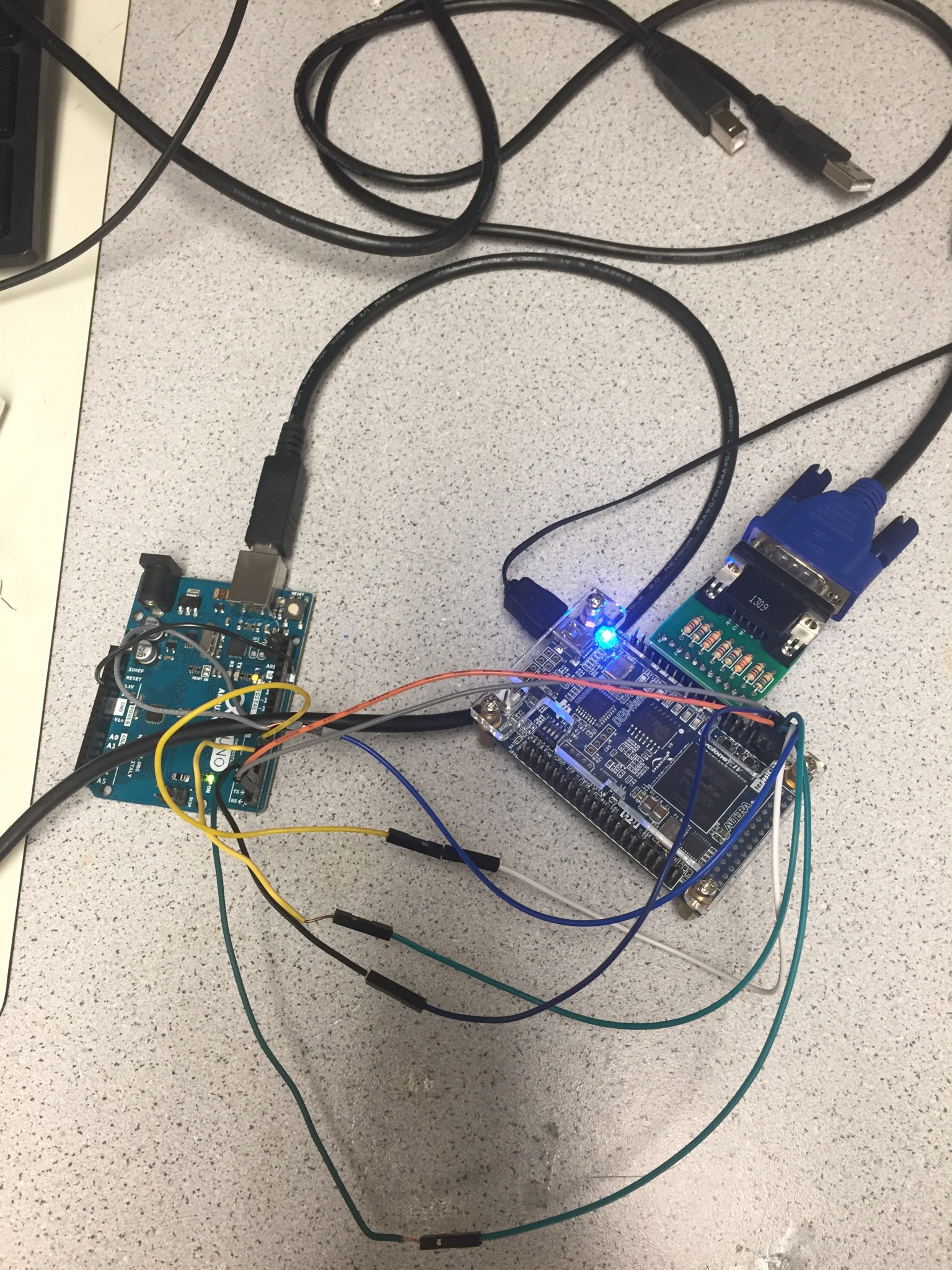
- We sent connected 7 output pins from the Arduino to GPIO pins on the FPGA.
- Within the code we set the inputs to the corresponding location x and y coordinates and data
(if treasure was found, location visited, etc).
The connections between the Arduino and FPGA are shown below.
3. Highlight the robots current location based on packet information
- In order to implement this, we used two for loops to check every square of the array.
- The output from the Arduino was sent to GPIO pins that stored the current x and y coordinates.
- In our for loop, if we were on the current coordinates, the grid_array value would be given red.
The rest of the grid within our grid size would be black, and all of the other coordinates would be given blue.
always @ (posedge CLK_1s) begin for (x=3'b0; x<=3'd3; x=x+3'b1) begin for (y=3'b0; y <= 3'd4; y=y+3'b1) begin if (x == highlighted_x && y == highlighted_y) begin grid_array[x][y] <= RED; visited[x][y] <= 1'b0; end else if (visited[x][y] == 1'b0) begin grid_array[x][y] <= GREEN; visited[x][y] <= visited[x][y]; end else begin grid_array[x][y] <= BLACK; visited[x][y] <= visited[x][y]; end end end end - Initially, we had the above always block execute whenever highlighted_x or highlighted_y changed,
but we changed that to every second because whenever highlighted_x or highlighted_y changed,
the always block would execute multiple times.
Having the block occur every second effectively debounced the changing signal from the Arduino.
                localparam secDiv = 25000000/2;
                reg [24:0] counter_1s;

                always @(posedge CLOCK_25) begin
                    if(counter_1s == 0) begin
                        counter_1s <= secDiv-1;
                        CLK_1s <= ~CLK_1s;
                    end
                    else begin
                        counter_1s <= counter_1s - 1;
                        CLK_1s <= CLK_1s;
                    end
                 end
4. Mark explored territory
- We created an array that stored whether or not we had already visited the coordinates corresponding to the coordinates in the grid_array, initializing all values to 0. visited[x][y] updates to 1 once coordinates (x,y) are visited by our current location. In drawing the grid using our for loop, if the current x and y of interest is marked as visited, we set it to green.
- Here is a video of the grid updating as the robot's position changes.
- Here is the code we used to simulate the robot moving through the maze:
              void setup() {
                // put your setup code here, to run once:
                pinMode(3, OUTPUT); // y lsb
                pinMode(4, OUTPUT); // y
                pinMode(5, OUTPUT); // y msb
                pinMode(6, OUTPUT); // x lsb
                pinMode(7, OUTPUT); // x msb
                pinMode(8, INPUT);
              }

              void loop() {

                while(!digitalRead(8));

                digitalWrite(7, LOW);//x msb
                digitalWrite(6, LOW);//x lsb
                digitalWrite(5, LOW);//y msb
                digitalWrite(4, LOW);//y
                digitalWrite(3, LOW);//y lsb
                // 0,0
                delay(1000);

                digitalWrite(7, LOW);//x msb
                digitalWrite(6, LOW);//x lsb
                digitalWrite(5, LOW);//y msb
                digitalWrite(4, LOW);//y
                digitalWrite(3, HIGH);//y lsb
                //0,1
                delay(1000);

                ... etc