Objective:
The objective of this lab was to test and familiarize ourselves with the sensors and signal processing needed for our robot to detect the acoustic and optical signals. We split into two subteams, one that worked with a microphone circuit to detect a 660 Hz whistle and another to work with an IR phototransistor to detect a treasure blinking at different frequencies. Both subteams used the Arduino Open Music Lab FFT library to process the data given by the sensors and create a filter allowing us to analyze the data.Team Division:
- Audio: Serena Krech, Alice Song, Victoria Tu
- Treasure: Meghan Chen, Rohit Krishnakumar, Michael Yee
Audio Team:
Materials used:- Electret microphone
- 1 µF capacitor
- 300 Ω resistors
- ~3 kΩ resistor
- LM358AN op-amp integrated circuit
Procedure:
- Read over FFT library
- Tested an example using function generator at 660Hz and other frequencies
- Used single mic - tested with clapping and a tone generator
- Build an amplifier (2)
- Switched to adafruit mic - built in amplification
- Tested mic at different distances
1. Read Over FFT Library:
- We read documentation about the FFT library
- We used fft_adc_serial as an example to see how the ADC worked as well as fourier transforms
2. Tested Example Code fft_adc_serial:
- Initially, we ran the code by using just the function generator and Arduino without the microphone

- fft_adc_serial saves a total of 256 data points because even though the for loop is i<512, it increments i by 2 and sets the odd bins to zero. After all the data is taken, it is reordered and processed in the fft
- We set the function generator at 660Hz and 1.5Vpp with an offset of 750mV

- We used the oscilloscope to verify our implementation

- We plotted the data generated from the code in Excel
- We repeated the process with different frequency values (multiples of 660Hz)
- The plot illustrates reasonable results, disregarding the first few points
- The first few points were disregarded since they were the exact same value for all frequency values
3. Testing with Microphone #1:
- We then built a circuit to connect the microphone to the Arduino
- We tested the FFT with a single microphone without any amplifying
- We used a tone generator app Function Generator to generate 660Hz for the microphone
- The results shown by the oscilloscope indicate a response, though the waveform amplitude was relatively small

- We also tested the microphone by clapping to see if the oscilloscope output reflected the change in sound
4. Building Amplifier #1:
- We first attempted to build a simple non-inverting amplifier for our microphone
- We used resistance values of 1000Ω and 10kΩ in order to achieve a gain of 10
- When then tested the output of the amplifier with an oscilloscope
- Our results were surprising because we did not see a change in the output
5. Using New Microphone:
- After attempting to build our own amplifier, we tried using Adafruit’s Electret Microphone Amplifier with Adjustable Gain. From the datasheet we learned that the board had a small trimmer potentiometer that we could adjust using a screwdriver. The potentiometer could adjust the gain from 25 times the original up to 125 times the original. The circuit that supports the op amp can be seen below.

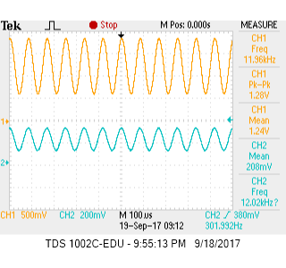
- Below are screen-captures from the oscilloscope depicting the amplified waveform.


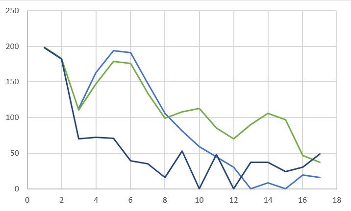
- In the graph below, the dark light blue line represents the output from the function generator at 660 Hz. The green line represents the output from the Adafruit microphone. The peak in bin five is the 660Hz Tone. This measurement was taken when the tone was played very closely to the microphone. When played further away, the dark blue line, the peak in bin five was less obvious, but still there. For this reason, we may attempt building another amplifier and a low pass filter for the circuit later on. This will help the robot better reconize the starting 660 Hz tone.
6. Testing Microphone at Different Distances:
- We also tested our circuit by placing the microphone at different distances to see how it affected our results
- We noticed that the tone was detected correctly, but the amplitude was much smaller (refer to graph above)
Treasure Team:
Materials used:- Arduino Uno
- IR receiver
- 300 Ω resistors
- 2 kΩ resistor
- Treasure board
- Solderless breadboard
Procedure:
- Read over FFT library
- Tested FFT output with square wave
- Assemble phototransistor circuit
- Test frequency of IR LED on treasure board
- Test phototransistor circuit output with treasure board IR learned
- Connect circuit to Arduino pins and use given FFT
- Plot output of FFT at different frequencies
1. Read Over FFT Library:
- We read the documentation provided (refer to Audio Team)
- The provided code used the ADC and because we are using the treasure boards at high frequencies like 17kHz, we continued to use the ADC, as the analogRead() function would not be fast enough
2. Tested FFT Output with Square Wave:
- We used the function generator to create a 7 kHz square wave
- We connected the output of the function generator to an analog pin on the Arduino
- We ran the fft code provided on the square wave data and collected the data
- Note: We tried using analogRead() as well, but this did not read fast enough to give discernible data between different frequency bins. This data can be seen below

- Instead we had to use the analog-to-digital converter
- We repeated this for 12 kHz and 17 kHz as well
- The ADC data is plotted below

- This data seemed reasonable and showed us that the fft was working
3. Assemble Circuit with Phototransistor:
- We assembled the circuit as shown in the picture below on a breadboard using the Arduino 5V and ground, a phototransistor, and a 2000 ohm resistor

- The phototransistor is being used to detect the IR LED on the treasure board so we used one that detects around 800 nm light (this is IR).
- The phototransistor allows current to pass under light so the circuit is completed when an IR light shines upon it
4. Test Frequency of IR LED on Treasure Board:
- We used a screwdriver to manipulate the potentiometer on the treasure board
- We probed the treasure board and checked that the frequency output was actually changing with the potentiometer
5. Test Phototransistor Circuit Output with Treasure Board IR LED:
- Using the oscilloscope we set the treasure board LED to 7 kHz
- We held the treasure board IR near the phototransistor
- We probed the circuit with the oscilloscope to view the output as we vary the distance between the treasure board and the photoresistor.
6. Connect Circuit to Arduino Pins and Use Given FFT Code:
- We connected the phototransistor circuit to the Arduino using analog pins
- We put a 300Ω resistor in the circuit to protect the Arduino pin
- We held the treasure board IR (still at 7 kHz) near the phototransistor
- We ran the provided fft sample code on the data the Arduino collected
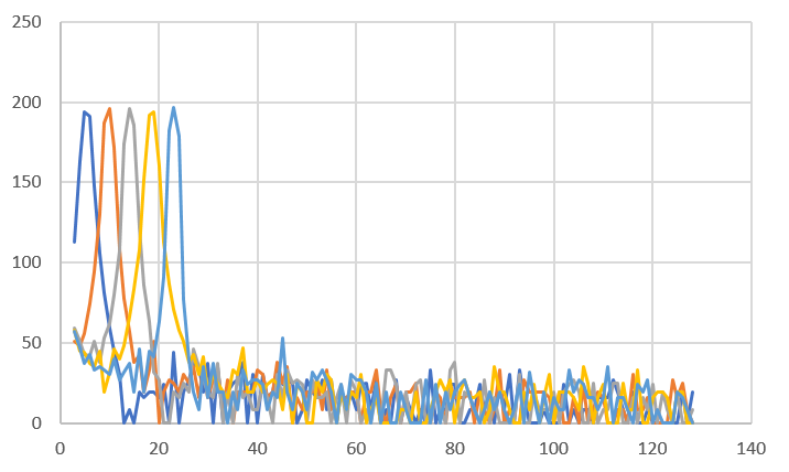
7. Plot Output of FFT for Treasure Board at Different Frequencies:
- We repeated the previous step but set the treasure board IR to 12 kHz and 17 kHz as well
- We collected the data outputted from the FFT for each frequency and plotted it on the same graph:
- This data shows discernible peaks for each frequency making us confident that our robot will be able to distinguish between the different treasures
8. Made Non-Inverting Amplifier Circuit
- Since the raw phototransistor signal was weak when the treasure board was too far, we had to build an amplifier circuit.
- We built a simple non-inverting op-amp circuit:

- We tested the circuit with a gain of about R2/R1 = 1k/180 = 5.6
- The actual gain was 1.24/0.208 = 5.96