Objective:
The objective of this lab is to work with an FPGA to begin the monitor display for the final robot as well as having the robot generate a "tune" using at least 3 tones.
Team Division:
- Graphics: Rohit Krishnakumar, Alice Song, Victoria Tu
- Audio: Meghan Chen, Serena Krech, Michael Yee
Graphics Team:
Materials Used:
- FPGA
- VGA switch
- Monitor
- Arduino
- Resistors: 1.7kOhms and 3.3kOhms
Procedure:
- Download example code on the FPGA
- Modify code to display a 2x2 grid
- Modify code to change grid color depending from the two switches
1. Download example code on the FPGA:
- Used VGA connector to connect the FPGA GPIO pins to the VGA switch
- Example code showed green screen on monitor and flashed green LED

- Modified code to display a different color on the monitor (red) 8'b111_000_00
- Drew a green square on a yellow background on the display

2. Modify code to display a 2x2 grid:
3. Modify code to change grid color from the two switches:
- Use highlighted_x and highlighted_y to modify the colors in grid_array
                always @ (*) begin
                  if (highlighted_x==0 && highlighted_y==0) begin
                    grid_array[0][0]<=8'b111_000_00;
                    grid_array[0][1]<=8'b000_111_00;
                    grid_array[1][0]<=8'b000_111_00;
                    grid_array[1][1]<=8'b000_111_00;
                  end
                  if (highlighted_x==0 && highlighted_y==1) begin
                    grid_array[0][0]<=8'b000_111_00;
                    grid_array[0][1]<=8'b111_000_00;
                    grid_array[1][0]<=8'b000_111_00;
                    grid_array[1][1]<=8'b000_111_00;
                  end
                  if (highlighted_x==1 && highlighted_y==0) begin
                    // etc... not shown for sake of briefness
                  end
                  if (highlighted_x==1 && highlighted_y==1) begin
                    // etc
                  end
                end
- First tested this by manually changing values of highlighted_x and highlighted_y
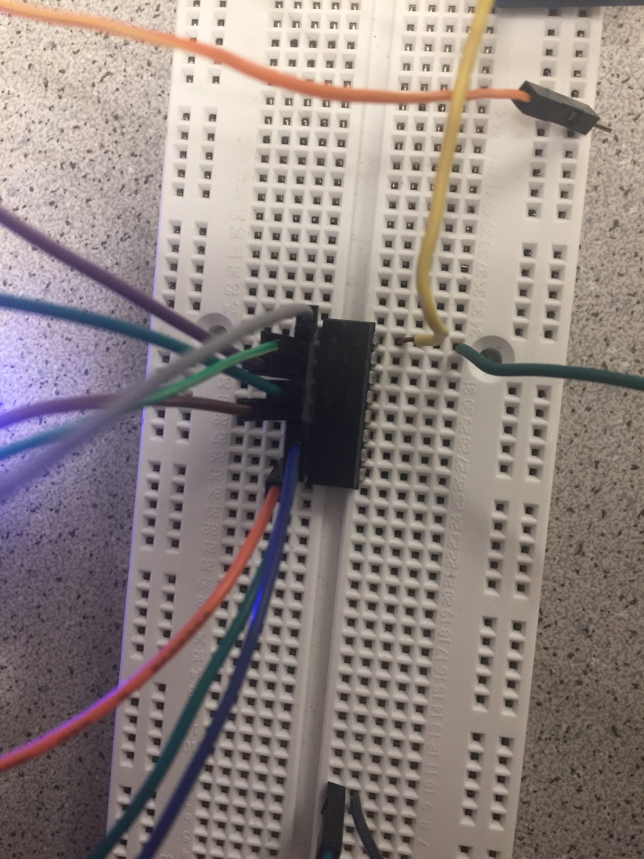
- Next, we wired up a circuit connecting the FPGA to an Arduino with 2 switches so that toggling the switches would modify the grid on the VGA display by setting highlighted_x and y based on these switches
- We wrote a simple Arduino sketch to output 5V when the switch is 1 and 0V when the switch is 0
                int readSwitch1 = 11;
                int writeSwitch1 = 10;
                int readSwitch2 = 2;
                int writeSwitch2 = 1;

                void setup() {
                  // put your setup code here, to run once:
                  pinMode(readSwitch1, INPUT);
                  pinMode(writeSwitch1, OUTPUT);
                  pinMode(readSwitch2, INPUT);
                  pinMode(writeSwitch2, OUTPUT);

                }

                void loop() {
                  // put your main code here, to run repeatedly:
                  if (digitalRead(readSwitch1) == 1) {
                    digitalWrite(writeSwitch1, HIGH);
                  }
                  else if (digitalRead(readSwitch1) == 0) {
                    digitalWrite(writeSwitch1, LOW);
                  }
                  if (digitalRead(readSwitch2) == 1) {
                    digitalWrite(writeSwitch2, HIGH);
                  }
                  else if (digitalRead(readSwitch2) == 0) {
                    digitalWrite(writeSwitch2, LOW);
                  }

                }
- Before testing the code, we first tested the voltage divider and two switches with a multimeter to verify our circuit
- The switch tells the arduino what to output which is then sent through the voltage divider and connected to the FPGA to set the highlighted_x and highlighted_y values.
- Initially we didn’t ground everything properly, so our display was a bit strange, but once we fixed that our screen showed the highlighted square changing grids when the switches were toggled.
Audio Team:
Materials Used:
- FPGA
- Arduino
- Lab Speaker
- Stereo Phone Jack Socket
- 8-bit R2R DAC
Procedure:
- Generate and play a square wave of a desired frequency
- Generate a more complicated waveform and play sound using the 8-bit DAC
- Turn on/off your sound with an enable signal
- Make a tune with at least three frequencies that plays when you receive a done signal from the Arduino
1. Generate and play a square wave of a desired frequency
2. Generate a more complicated waveform and play sound using the 8-bit DAC
3. Turn on/off your sound with an enable signal
- The FPGA reads in the signal from the Arduino in the input pin GPIO_0_IN[0], polling every second. If GPIO_0_IN[0] is HIGH, the start tone arpeggio plays.
- To test this functionality, we repeatedly sent two-second signal pulses from digital pin 2, set apart by 5 seconds.
- Below is the code we used to output the signal from the Arduino to the FPGA.
              void setup() {
                // put your setup code here, to run once:
                pinMode(2, OUTPUT);
                Serial.begin(9600);
                digitalWrite(2,LOW);
              }

              void loop() {
                // put your main code here, to run repeatedly:
                delay(5000);
                Serial.println("done");
                digitalWrite(2, HIGH);
                delay(2000);
                digitalWrite(2, LOW);
                Serial.println("done signal off");
              }
- Below is the section of the code for the FPGA that we needed to edit in order for the sound to play when it received the done signal.
              always @(posedge CLK_1s) begin
                if (GPIO_0_IN[0] || (soundCount > 3'b0 && soundCount <= 3'd3)) begin
                  if (soundCount <= 3'd3) begin
                    soundCount <= soundCount + 1;
                  end
                  else begin
                    soundCount <= soundCount;
                  end
                end
                else begin
                  soundCount <= 3'b0;
                end
               end
4. Make a tune with at least three frequencies that plays when you receive a done signal from the Arduino
- We made an arpeggio by generating a sine wave in matlab and sampling it at different rates with different clock cycles (1000, 1250, and 1500 Hz) and played each tone for one second each.

- The above wave form shows an inconsitency in the waveform that occurs in the same location in each cycle. Due to this the tone was not as clear. Since this problem was so consistent, we turned to our sine table to look for a possible cause. We then realized that while out sine table only had 8-bit values, it was ranged between 0 and 256. This meant that every time it went out of bounds, we were going to get a deiscrepancy. Once we fixed the few balues that were out of bounds we were able to play a clear sine wave and move on to generating multiple frequencies.
- To generate the tones, we used a counter for each respective sampling frequency to traverse the sine table and produce the signal to the output.
- We used another counter to keep track of the signal that was currently playing. This counter increments every second to change the sampling frequency and change the tone playing as a result. Once the counter reaches 4, we stop playing the tone.
- The tones only begin playing when the board receives a signal from the Arduino.